Creating a servo driver using the NE555 timer IC is one of the simplest and most effective ways to control a servo motor for robotics, automation, and DIY electronic projects. The NE555 is a versatile and inexpensive integrated circuit that can generate precise pulse-width modulation (PWM) signals—exactly what a servo motor requires for accurate position control.
A typical RC servo motor operates with a control pulse between 1 ms and 2 ms repeated every 20 ms (50 Hz). A 1 ms pulse moves the servo to one end (0°), a 1.5 ms pulse centers it (90°), and a 2 ms pulse moves it to the other end (180°). The NE555, configured in astable or monostable mode, can generate these variable-width pulses.
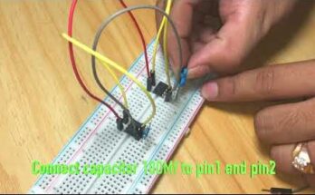
To build the circuit, connect the NE555’s pin 8 to +5V, pin 1 to ground, and use resistors and a potentiometer connected between pins 7, 6, and 2 to control the timing. Pin 3 outputs the PWM signal that drives the servo’s control line. A variable resistor (potentiometer) lets you adjust the pulse width, changing the servo’s angle smoothly. Adding a small 0.01µF capacitor between pins 5 and ground helps stabilize the signal.
For better precision, use a 10kΩ potentiometer and fine-tune resistor values (typically between 1kΩ and 47kΩ) to set the frequency around 50 Hz. The circuit can be powered by a regulated 5V supply, which is ideal for both the NE555 and most servo motors.
This simple NE555-based servo driver is reliable, inexpensive, and perfect for beginners learning about PWM control. It can be used in robot arms, RC models, automatic doors, and sensor-based systems—demonstrating how powerful and flexible a single IC can be in controlling motion accurately.